How to detect and enable Sustain again and patch the existing SW ?
Since no additional I/O is available on the SOC in order to manage an external Sustain Pedal, my idea is to use the analog input normally used to detect the HeadPhones Jack.
(PSS-A50 has two analog inputs : one to detect the jack (AN1) and another one to measure the batteries voltage (AN0) in order to shut down when this voltage is too low).
Since the jack detection is done using an analog input, it is able to measure different voltage values.
If I add some resistors in from of the analog input in order to create new voltage levels depending on the combination jack inserted / sustain pedal pressed, we’ll have the trick !
1°/ HW modifications :
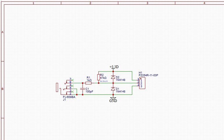
My choice is to add two resistors (see schematics below) :
RS = 33k in the new Sustain Jack path
RH = 22k in the HeadPhones Jack detection path (some traces need to be cut in order to place this resistor)
Now, there’s a new voltage divider involving R113, R608, RS and RH.
This is in order to have a relative important delta value between the different combinations we have with Pedal/headphones and also resistors tolerances, and also depending on the piano is battery or USB powered
(analog values read are not the same depending on the power source; which is strange since Vref is taking the regulated 3.3V –and not a Vref voltage - ; but the 3.3V is quite stable, either the power source is batteries or usb).
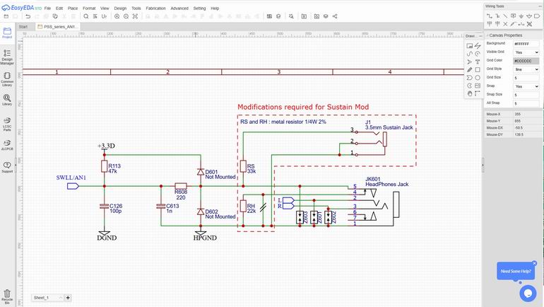
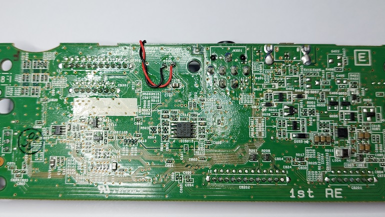
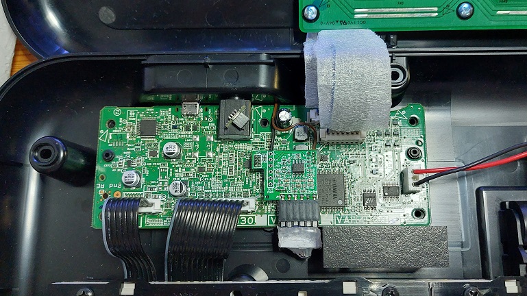
At first, open your PSS-A50. Remove the flat cables from the main board, unscrew the main board, add a 22k resistor under the PCB, between a pin from the stereo headphones jack and the ground.
For that, four small traces on the PCB are needed to be cut (blue circle). Check the (absence of) continuity to confirm the traces are cut properly (the pad just on the left still has its four traces) :

Then, solder the 22k resistor between this pin and the ground :

When no jack is inserted, there’s a contact between the pins in the blue circle. If a jack is inserted, it’s an open circuit.
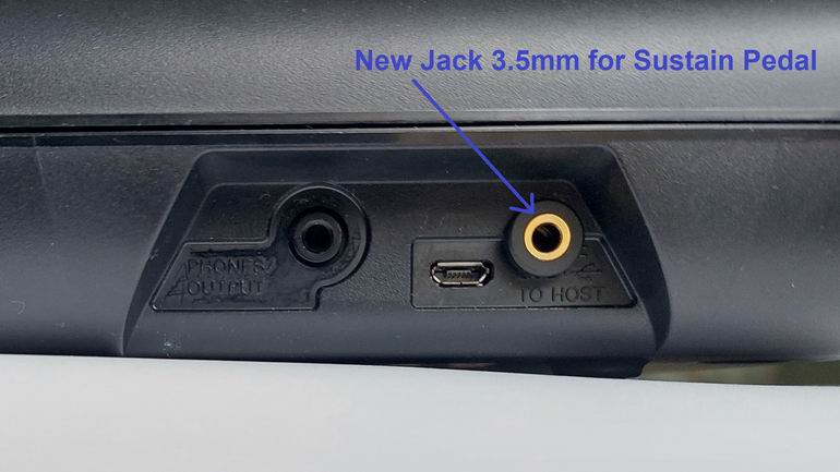
While the PCB is unscrewed, drill a hole in the lower plastic case, close to the usb connector, in order to fit a 3.5mm female jack. My choice was to use a 3.5mm jack in order to fit nicely to the case. Then, I use a small adapter cable male 3.5mm <-> female 6.25mm in order to connect a standard Sustain Pedal :
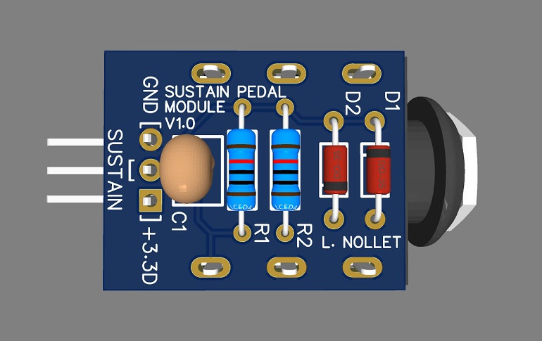
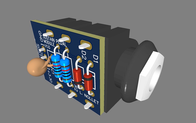
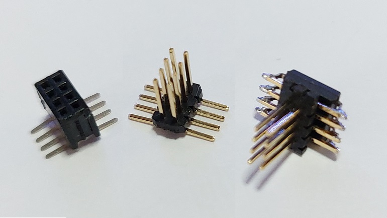
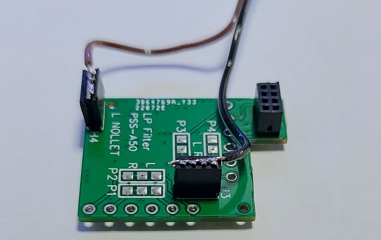
Prepare the 3.5mm female Jack in order to solder a 33k resistor on the “signal” pin (is a stereo jack is used, solder L+R together). A basic connector is needed in order to be able to connect/disconnect easily from the PCB. I used male/female 2.54mm headers :


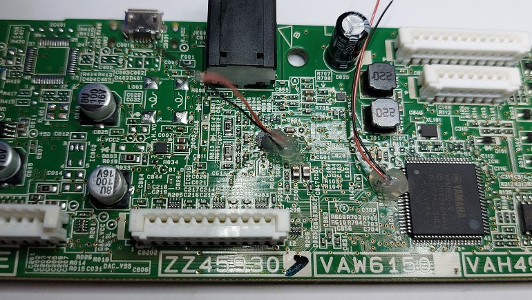
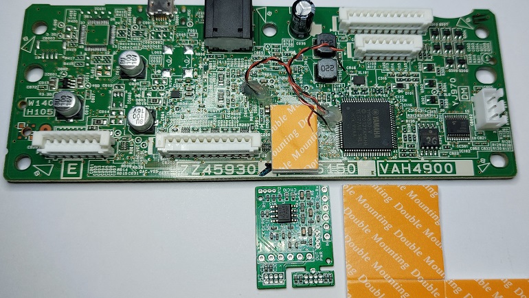
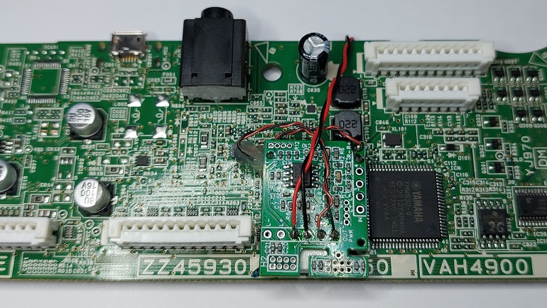
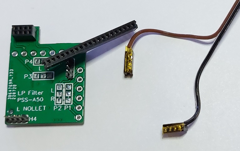
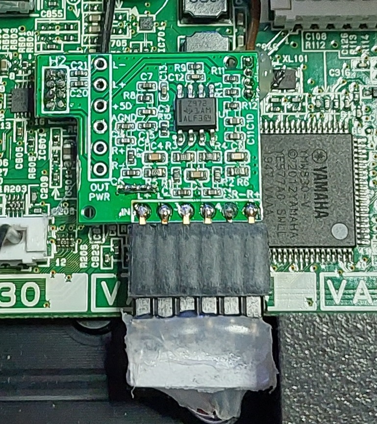
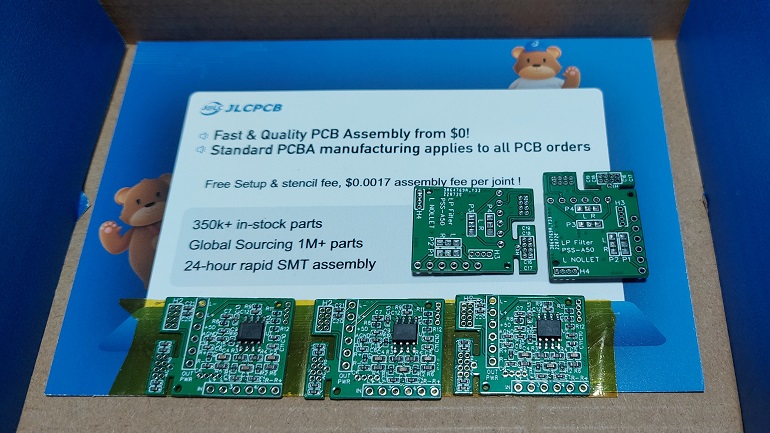
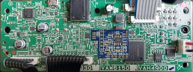
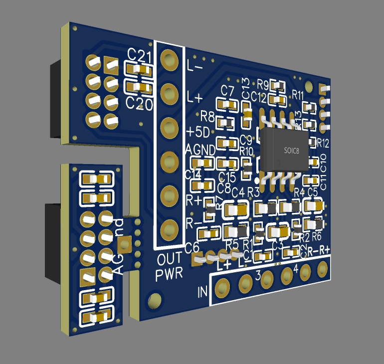
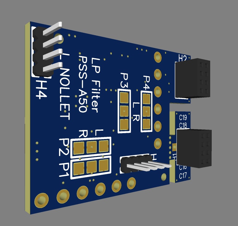
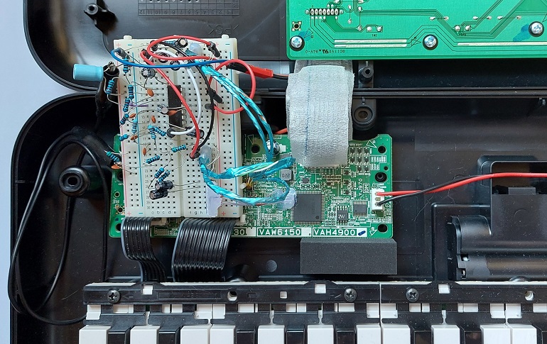
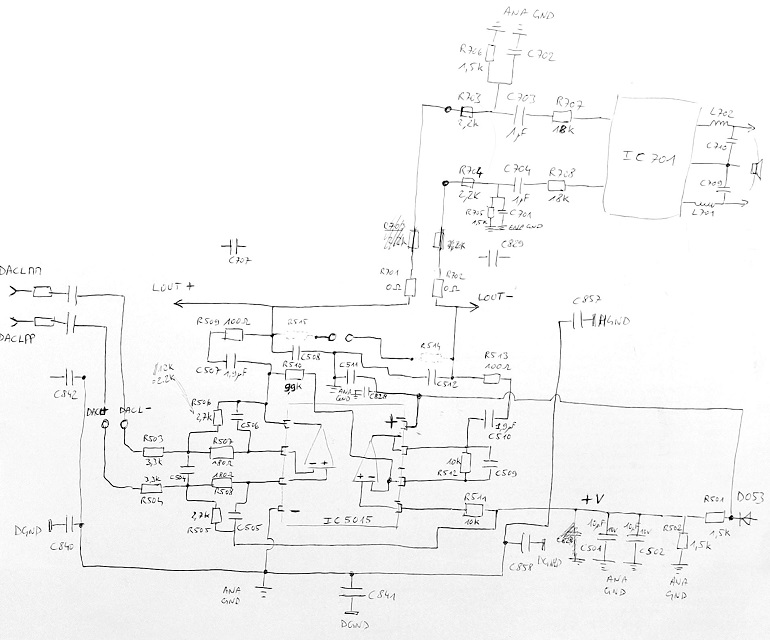
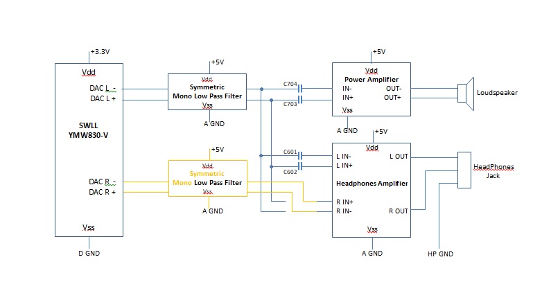
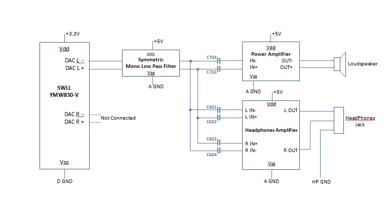
Here’s the internal view (with my stereo mod pcb) :

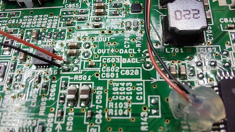
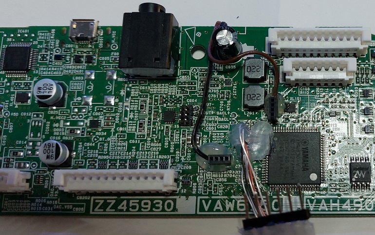
Wires shall be soldered on the PCB, on the following unused pads of D601 / D602 :

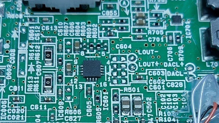
Now, more difficult, desolder the flash memory. This is required in order to read and modify the SW binary.

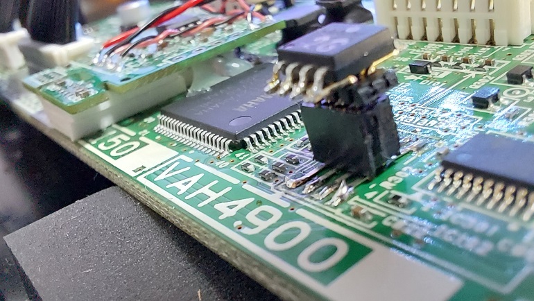
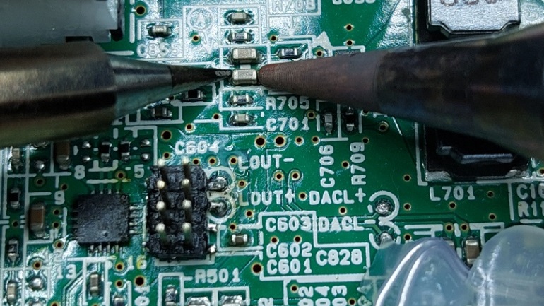
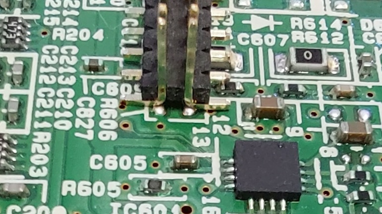
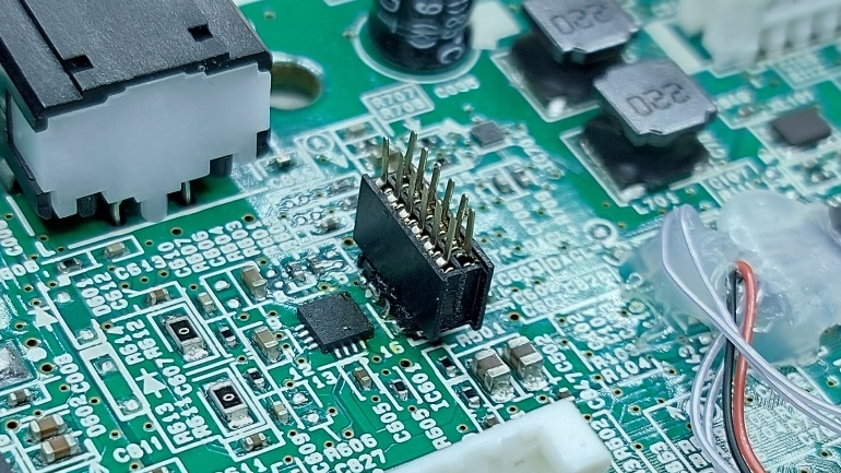
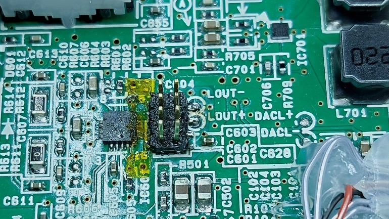
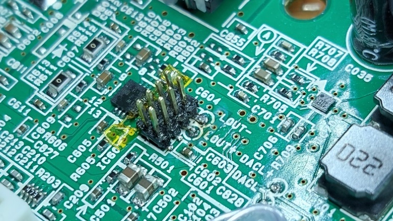
Since I needed to instrument the HW in order to read/write the flash and to retroengineer the sw and get some traces, it was easier to put the flash on a header.

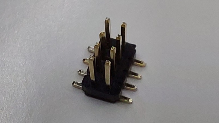
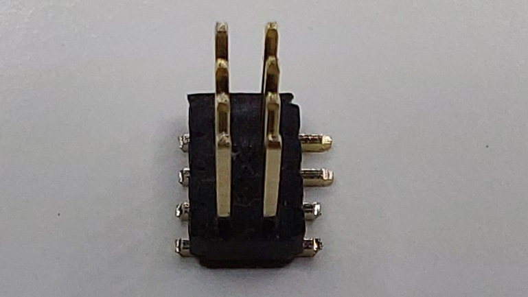
I used a female 1.27mm header on the pcb and adapted a male 1.27mm header with 45° pins in order to fit in the female pcb header.

And finally, I used a cheap flash memory programmer in order to read and modify the SW :

Reminder about the Yamaha Sustain Pedal :
Pedal needs to be plugged BEFORE you turn the piano on. This is expected by Yamaha (part of the user-guide)
The switch inside the pedal is ON when the pedal is released (by default).
The switch inside the pedal is OFF when the pedal is pressed.
Yamaha implemented a SW strategy (which is still present here) in order to always behave the right way either a pedal is plugged or not when turning the piano on.
Also, this helps to manage the two different kind of pedals you have on the market, and when the pedal is released (“ON” logic or “OFF” logic)
2°/ Evaluation of the values for the thresholds in order to make the difference between the possible combinations :
Digital Values read depending on the combinations :
COMBINATION                               MEASURED    THEORY (with 22k/33k)

Powered by USB / No Headphones :
Sustain Pedal plugged           Released  0394        038D
                                Pressed   0510-0514   0522
Headphones connected :
Sustain Pedal plugged           Released  0680        06A0
( = Sustain Pedal unplugged)    Pressed   0E4C-0E50   0FFF


Powered by 4xAA / No Headphones :
Sustain Pedal plugged           Released  03D4         038D
                                Pressed   056C-0570    0522
Headphones connected :
Sustain Pedal plugged           Released  06F4-06F8    06A0
( = Sustain Pedal unplugged)    Pressed   0F44-0F48    0FFF
Considering these measures, let’s determine the right thresholds in order to make the difference between the combinations (threshold value is the value in-between) :
USB Measures    Threshold
0394
                0x0452
0510-0514
                0x05CA
0680
                0x0A66
0E4C-0E50

4xAA Measures   Threshold
03D4
                0x04A0
056C-0570
                0x0632
06F4-06F8
                0x0B1E
0F44-0F48
Now, let’s determine the final thresholds in order to fit with the differences we have depending on the power supply (threshold value is also the value in-between):
Final Thresholds for SW :
0x0479 (between 0x0452 and 0x04A0)
0x05FE (between 0x05CA and 0x0632)
0x0AC2 (between 0x0A66 and 0x0B1E)
3°/ SW Modifications :
A SW patch is required in order to activate the right functions depending on the combinations.
This SW patch is more tricky to implement since NO information are available.
Nothing about the µC/SOC and the tone generator, nothing about the mapping, the registers... NOTHING.
A lot of retro-engineering was required to identify the entry points.
Sustain management was already present in the software, but not "connected" to the right functions since on PSS-A50, no more I/O was available for that (at the opposite of the PSR-F51 for which the Port C0 was still available and functional).
Two functions are involved and might request a patch since they both use AN1 :
- The function that detects a jack insertion (in order to switch between headphones/loudspeakers when a jack is inserted)
- The function that detects a sustain request (sustain pedal pressed/released)
A/ Jack detection :
Location : @7ed7c in µC memory map (@3ed7c in Flash)
undefined4 FUN_Return_AN1_I/O_0_or_7f_0007ed7c(void)
{
  int iVar1;

  iVar1 = FUN_Read_Analog_I/O_ANx_P1=0:AN0_P1=1:AN1_00060cdc(1);
  if (0x3e < (iVar1 >> 5 & 0xffU)) {
    return 0x7f;
  }
  return 0;
}
This function measures analog input AN1, lowers (>>5) the native 12bits resolution to 7 bits (0-7F), and considers a threshold value at the middle of the range (0x3E in the C pseudo code; but 0x3F in the flash).
Then, it returns 0x7F or 0 depending on the presence of the jack.
Because of the resistors added, the threshold value to make the difference between Headphones jack inserted or not has to be changed (0x3E does not fit anymore). Value in the code is the 8 bits MSB of the 12bits full resolution)
The new threshold (see above) is now 0x05FE (12 bits) when in the initial SW it is 0x7C0 (0x7C0>>5 = 0x3E +1=0x3F )
0x5FE>>5 = 0x2F (instead of 0x3E) => 0x2F + 1 = 0x30
=> if (0x30 < (iVar1 >> 5 & 0xffU)) {
B/ Sustain request detection : detects a sustain request (if uVar1==0xFF)
This function is currently “disabled” since uVar1 is always “0” (because value returned by FUN_Nothing_return_0_0007e9ec(param_1)); while param_1 is supposed to be 0/1 to read the right analog input (on PSS-F5x) – or GPIO (on PSR-E2x3 )
(this function is called periodically by the system)
Retro-engineering the PSS-F51 and PSR-E253 firmwares could help to confirm.
void FUN_Jack_028c54+9=028c5d_0007e996(int param_1)
{
  uint uVar1;
  undefined uVar2;

  if ((&DAT_000bcbdc)[param_1 * 3] == '\0') {
    uVar1 = FUN_Nothing_return_0_0007e9ec();
    if ((&DAT_000bcbe8)[param_1 * 0xc] == '\0') {
      if (uVar1 == 0) {
        uVar2 = 0;
      }
      else {
        uVar2 = 0xff;
      }
    }
    else {
      uVar2 = (undefined)(uVar1 >> (uint)(byte)(&DAT_000bcbe9)[param_1 * 0xc]);
    }
    (&DAT_00028c5d)[param_1 * 0x10] = uVar2;
    FUN_0007e98c(param_1,(&DAT_00028c5d)[param_1 * 0x10]);
  }
  return;
}
This function manages a sustain request and changes some values in RAM and calls a function. This will affect later some registers in the Tone Generator that are involved in sustaining the 0 to 31 channel currently playing the current note/voice
The trick is to patch the FUN_Nothing_return_0_0007e9ec :
In the existing SW, this function does nothing, except returning “0”; meaning no sustain pedal pressed.
undefined4 FUN_Nothing_return_0_0007e9ec(void)
{
  return 0;
}
Unfortunately, the patch I have to write is longer than the space occupied by this function in the flash.
It means I have to locate my patched function elsewhere (at the end of the binary).
The address will be @0BD940 in FLASH (@0FD940 is SOC memory Map since there’s a 0x40000 offset)
Starting from this address, there are a lot of 0xFF (spare area).
Therefore, instead, I’ll write and call my own function : FUN_Read_Analog_IO_Sustain_000fd940(1);
C/ My own function, in C language, considering the thresholds :
#define   NOHP_NOSUS  0x0479
#define   NOHP_SUS    0x05FE
#define   HP_NOSUS    0x0AC2

uint32_t FUN_Read_Analog_IO_Sustain_000fd940(uint32_t r0)	// r0 = 1 to read AN1
{
uint32_t r1;

    r0 = FUN_Read_Analog_IO_ANx_P1=0:AN0_P1=1:AN1_00060cdc(r0);
         // r0 contains the analog value of AN1 (12 bits)

    if (r0 < NoHP_NoSus) {
        r0 = 0xFF;  // No Headphones / No sustain
    }
    else if (r0 < NoHP_Sus) {
        r0 = 0x00;  // No Headphones / Sustain
    }
    else if (r0 < HP_NoSus) {
        r0 = 0xFF;  // Headphones / No Sustain
    }
    else {
        r0 = 0x00;  // Headphones / Sustain
    }
return r0;
}
And the equivalent, in Armv7 ASM language :
FUN_Read_Analog_IO_Sustain_000fd940(uint32_t r0);
; r0 = 1 to read AN1
     push	{r7,lr}
     bl	0xFFF6339C
     ;= 60cdc - fd940
     ;Call FUN_Read_Analog_IO_ANx_P1=0:AN0_P1=1:AN1_00060cdc(r0)
     ldr	r7,RAM
     str	r0,[r7,#0x0]   ;Write AN1 analog value at memory @ 3f000 (debug/log)

     ldr	r7, NOHP_NOSUS
     cmp	r0, r7
     blt	NOSUS

     ldr	r7, NOHP_SUS
     cmp	r0, r7
     blt	SUS

     ldr	r7, HP_NOSUS
     cmp	r0, r7
     blt	NOSUS
SUS:
     movs	r0, #0x00
     pop	{r7,pc}
NOSUS:
     movs	r0, #0xFF
     pop	{r7,pc}

RAM:
.word     0x0003f000
NOHP_NOSUS:
.word     0x0479
NOHP_SUS:
.word     0x05FE
HP_NOSUS:
.word     0x0AC2
In the ASM, I added a debug trick in order to read the AN1 analog value from the RAM memory @ 03f000
     ldr	r7,RAM
     str	r0,[r7,#0x0]   ;Write AN1 analog value at memory @ 3f000 (debug/log)
This needs to be removed in final SW (put 00 00 00 00 instead of 4f 07 60 38; means “movs r0,r0”; kind of NOP)
And finally, the bytes to change and to add in the memory flash :
(@Adresses are given from the Flash memory, means it starts from 0x000000)
Only 60 bytes are able to enable the “Sustain Pedal” function. They are in bold below !
It is just needed to change the values given (in bold) in each of the 3 “Patch” sections below
A/ Jack detection :
Initial @03ED80 :
F7 E1 FF AC 11 40 06 00 0E 00 28 3F DB 01 20 7F

Patch @03ED80 :
F7 E1 FF AC 11 40 06 00 0E 00 28 30 DB 01 20 7F
B/ Sustain request detection : Jump to the patch instead of calling the initial function
Initial @03E9A0 : (“F0 00 F8 20” is the offset to reach “FUN_Nothing_return_0_0007e9ec”)
5C 08 28 00 D1 1A 1C 38 F0 00 F8 20 00 79 19 C9

Patch @03E9A0 : (“1C 78 means “adds r0,r7,#0x1” in order to pass “1” as a parameter to read “AN1” and (“F0 7E FF CA” is the offset to reach “FUN_Read_Analog_IO_Sustain_000fd940”)
5C 08 28 00 D1 1A 1C 78 F0 7E FF CA 00 79 19 C9
C/ Patch/New function in order to manage the combinations / thresholds (ARM thumb) :
Use "Patch @0BD940 : (without debug)" below
Initial @0BD940 :
FF FF FF .. .. ..

Patch @0BD940 : (with debug)
B5 80 F7 63 F9 CB 4F 07 60 38 4F 07 42 B8 DB 07
4F 06 42 B8 DB 02 4F 06 42 B8 DB 01 20 00 BD 80
20 FF BD 80 00 03 F0 00 00 00 04 79 00 00 05 FE
00 00 0A C2 FF FF FF FF FF FF FF FF FF FF FF FF

Patch @0BD940 : (without debug)
B5 80 F7 63 F9 CB 00 00 00 00 4F 07 42 B8 DB 07
4F 06 42 B8 DB 02 4F 06 42 B8 DB 01 20 00 BD 80
20 FF BD 80 00 03 F0 00 00 00 04 79 00 00 05 FE
00 00 0A C2 FF FF FF FF FF FF FF FF FF FF FF FF
Plug the flash memory on the PCB, plug a sustain pedal, turn on the PSS-A50 and enjoy !
Youtube : PSS-A50 Sustain Pedal

