PSS A50 stereo mod : The 1.27mm 2x4 pins mod
By lionel nollet on Monday, July 18 2022, 18:03 - Permalink
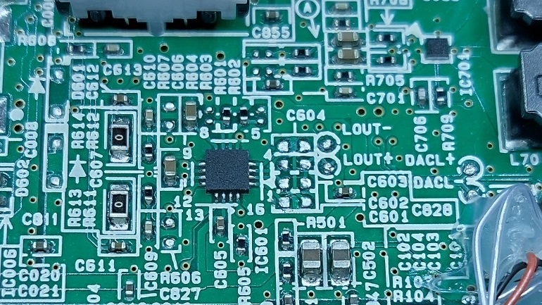
First step is to remove C601/602/603/604 and adjust and solder a 8 pins 1.27mm male smd header (2x4) in order to have something clean :
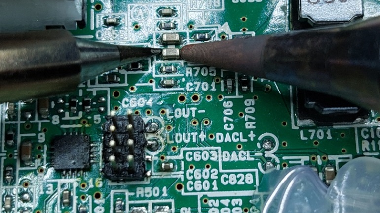
The easy way for me to desolder the caps is to use two irons, in order to prevent heating too much. My brand new TS100 with the TS-I tip on the left, and my old good JBC30S with R05D round tip on the right (the smallest available).
This pic is for illustration only (the header is already soldered; The iron tips are on another cap, just for the picture).
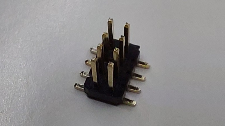
Then, the 1.27mm header has to be adjusted before beeing soldered :
The two top-right pins stay at their nominal length
The two pins below are cut at the half length
The four pins on the left are cut that way only one third of the length remains
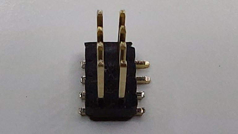
The picture below is for illustration only, since the header is not located on C601-604. As you can see, bottom parts of the smd header is located exactly on the pads.
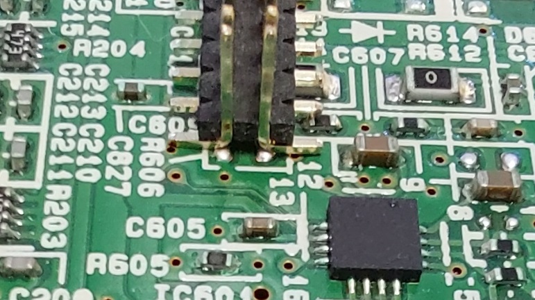
Alignment of the header is a crutial operation, because the pads on the PSS-A50 PCB are not exactly designed for this kind of header. It is very risky if you are not experienced or if you don't have the right iron / tip. Don't do it if you are not used or fell uncomfortable.
The result after the soldering operation :
(it looks dirty on the picture because of the flux, but the header is in a well condition and not melted).
During the soldering, it's mandatory to have the female conterpart connected on the header in order to avoid having the pins bent.
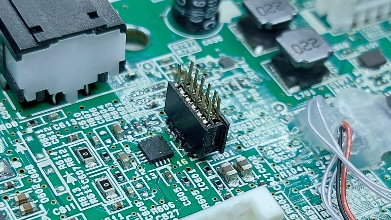
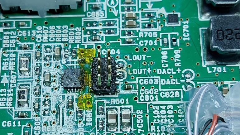
I used Kaptan tape in order to protect the headphone amplifier from the heat and avoid any solder projection on the 4 very tiny pins of the chip. This is a chinese "Koptan". The quality is not very good and might melt if heated too much. Once the header was soldered, I removed the tape. I also used a flux gel in order to ease the soldering and ease the capillarity.
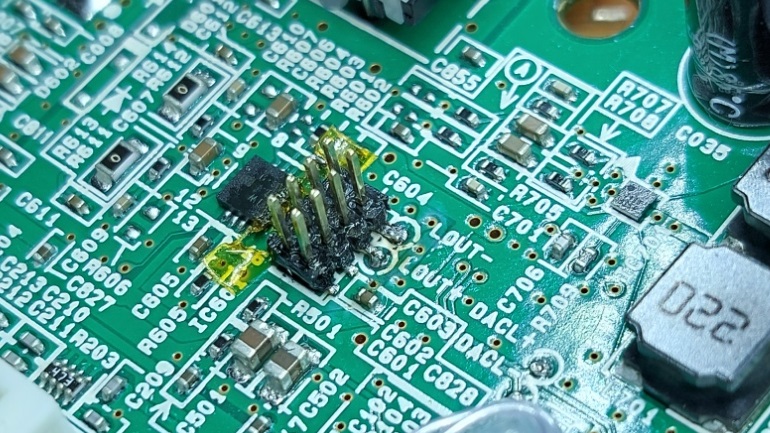
Once soldered, check for every pins, and also cross-check that there is no short circuit and no open connection
1 x x 8 ("L OUT-" written on the PCB, from existing OpAmp)
2 x x 7 ("L OUT+"written on the PCB, from existing OpAmp)
3 x x 6
4 x x 5
pins 6 and 7 are shorted, because of the PCB trace, that's normal.
pins 5 and 8 are shorted, because of the PCB trace, that's normal.
pins 1 to 4 are going respectively to the close pins of the headphone amplifier IC
You can use a needle in order to have a thinner test point with your multi-meter in order to check the continuity and absence of short circuit
Comments
WOW, really GREAT job! A+++++