PSS A50 stereo mod : mod PCB Assembly with PSS PCB
By lionel nollet on Thursday, July 21 2022, 13:32 - Permalink
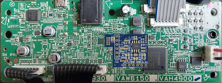
The PCB design is close to be frozen
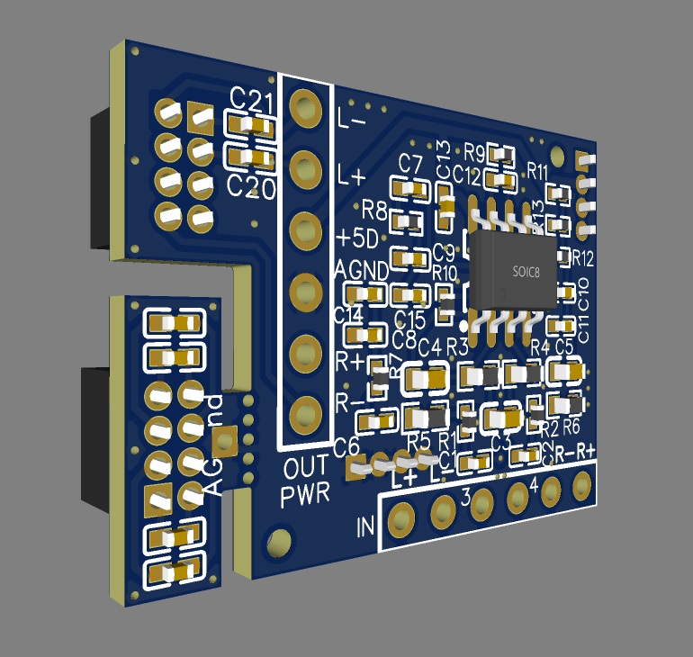
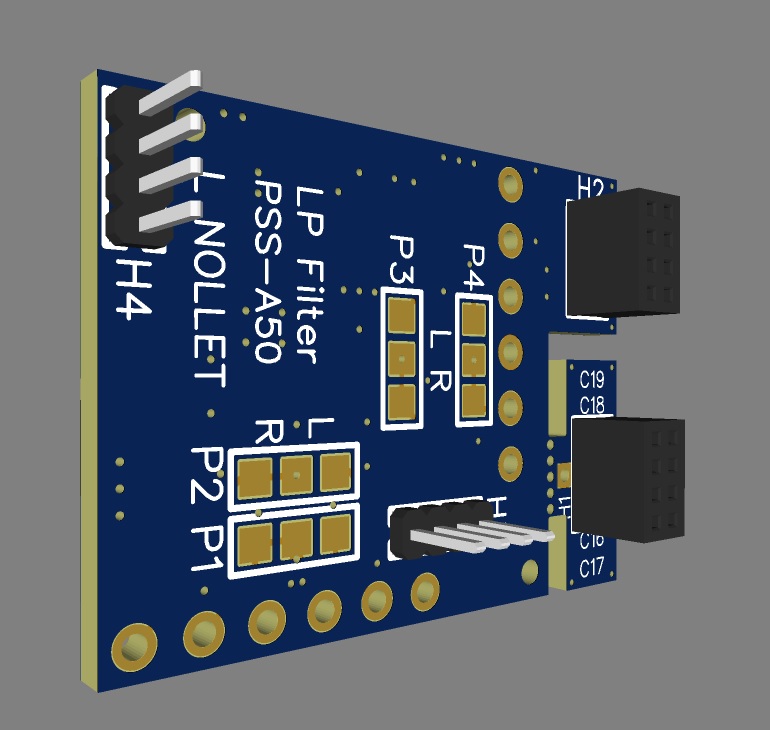
On the top left corner, the 2x4 pad for the female header (bottom of the PCB)
In case your iron ability is not proven to solder a 1.27mm header on the PSS PCB, it's still possible to solder just 2 wires from the PSS PCB (near the headphones amp; C601 and C602 to be removed) and the 2.54mm pads on the left side of my PCB (OUT : R- and R+)
Two wires are also needed from the DACRPP/DACRMM pins of the Yamaha SWLL YMW830-V IC; to be soldered on the 2.54mm pads on the bottom side of my PCB (IN : R- and R+)
And last but not least, two wires for the power supply (to get from the capacitor C035 (under the PSS PCB) on the 2.54mm pads on the left side of my PCB (+5D, AGND)

I used two 1x4 pins 1.27mm headers (bottom left and top right) that are used as a spacer (same height as the 4x2 male + female header) in order the PCB keeps well in place (two 4 pins male headers soldered under my PCB, and two 4 pins female headers glued on the PSS PCB)
The PCB has a breakable part in order to be plugged on the male 2x4 header, soldered on the PSS PCB (in case we decide to remov the mod and find the original mono sound configuration.


Comments
Yes-yes-yes! Awesome!