PSS A50 stereo mod : mod PCB integrated PSS PCB : details
By lionel nollet on Saturday, October 8 2022, 20:42 - Permalink
I'm happy with my integration. I now enjoy a lot playing with my PSS-A50.
It's a real pleasure, especially when playing with headphones.
To begin, have a look on my latest video : I hope you'll enjoy the all world around known "Get Lucky".
Maybe it's the first time this song (kind of intro in fact) is played (at least on youtube) on a Yamaha PSS-A50.
And for sure, it's the first time on a stereo PSS-A50.
https://youtu.be/QGN_a2lWWMY
Please also have a look there (he was inspired by my mod) : https://darekasan-net.hatenablog.com/entry/2022/09/19/045703
(Chrome can translate in case)
DarekaSan implemented an additional jack output using a PCB shield for Raspberry Pico (it seems the PCB is only available in Japan), and cut the PCB shield to isolate the lowpass filter section.
In this implementation, no stereo sound will be connected to built-in PSS-A50 headphones jack.
About my own PCB integration, here are some details :
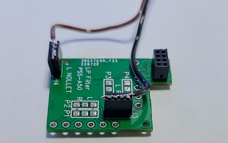
At first, I soldered two 4 pins male headers (1.27mm) on my PCB (H3 and H4).
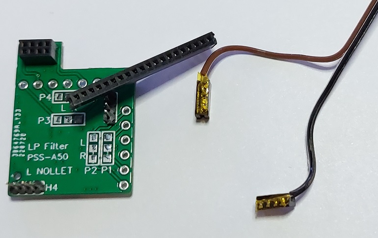
Then, I inserted two 4 pins female headers (1.27mm) and soldered two wires : black on female H3 for AGND and red for female H4 +5V

The pins of the female headers have been bended in order to lower the header profile
Also, don't forget to solder on the mod PCB a 6 pins 2.54mm female header (or, in case, only 2 pins may be enough just for the R+ / R- RIGHT channel) in order to plug the wires coming from of the Yamaha SWLL YMW830-V IC.
I also put some "Koptan" (the Chinese low quality Kaptan) in order to have an insulation with the PSS-A50 PCB; because the idea is :

1. Plug the female headers on the Mod PCB male header
2. Put some hot Glue on the PSS-A50 PCB (at the places where the two 4 pins headers will be, once the mod PCB will be pluged on the 2x4pins male header I soldered the last time on the PSS-A50 PCB
3. While the glue is still hot (don't waste time), plug the PCB mod at the right place on the PSS-A50 PCB
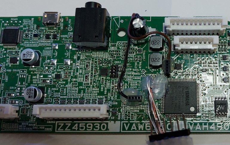
4. Solder the red and black wires on the Capacitor C035 pins (on the bottom of the PSS-A50 PCB)
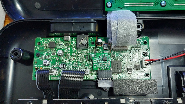
The assembly will look like this :

If you unplug the mod PCB, here's how it looks like :

That way, the mod PCB is mecanically firmly inserted in three locations, which makes it stable from a mecanical point of view.
Anyway, I'm aware the fragile location (or weak point) is the 2x4pins male header soldered on the PSS-A50 PCB, because the original PCB pads are not suited to hold this kind of component. In order to make the meca more robust, it would be relevant to put some cyanoacrylate glue around the PSS-A50 PCB and the bottom of the 2x4pins male header (once soldered of course).
Comments
Great! No plans to make a couple of boards for sale? I'm first to buy it!